Design 1

AutocaDesigner

Design 2

AutocaDesigner

Design 3

AutocaDesigner

Design 4

AutocaDesigner

Design 5

AutocaDesigner

Wednesday 26 June 2013

A very important part of any drawing is placing dimension lines, but this process must be done in a proper way. There are certain rules that has to be followed in order to highlight all the needed details to produce correct and easy to understand designs ready to be constructed. So, I am going to show you several common mistakes that are made in various situations and ways to avoid them.


 1) The dimension lines should be thin, the arrows should have proper size and the numbers should be at the correct place.


 2) When there is not sufficient space we must place the arrows, even the numbers outside of the specific area.


 3) Design lines should not be used to display dimension lines.


 4) Design lines should not be ''interupted'' when possible.


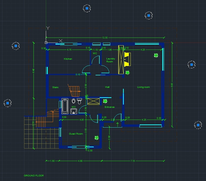
5) Dimenstion lines should be placed in such a way to avoid confusion.

 7) Every dimension have to be displayed once at the best possible location.


8) When a hatch is applied, dimension lines should be placed outside the object. However, we can put the dimension line inside the hatched object but the hatch lines have to be interrupted around the number.

Monday 10 June 2013

Let's say that we want to add text in our drawing. There is an easy way to create a new single line style and customise it until we are pleased.


The first thing to do is to open our drawing and go to annotate on the ribbon menu.

Figure 1 - Annotate Menu


At the down right corner there is an arrow that opens the text style menu.

Figure 2 - Text style menu

At this point we can see that the only available style is the standard one. So, we have to create a new style by pressing the New button. After we have chosen a name for our new style, then we can customise text style until we are satisfied.

In our example, we want to have a specific height for our text. So, every time we add text, the height will be predefined. 

  • Height of the text is set to 0.3
  • Font style is changed to Bold.
  • Apply, Set current.
 From the annotate ribbon we can see the multiline button. By pressing it, single line text is revealed.

Figure 3 - Selecting Single Line Text


When we have selected where to place our single line text the program skips the part where we have to specify the text height because it is predefined. However, we still have to specify rotation angle of text as shown below.

Figure 4 - Adding Text

In this case we write GROUND FLOOR and then we press enter twice to exit from text edit menu.

Figure 5 - Mission Accomplished


Thursday 6 June 2013


Figure 1 - Quick Selection icon
Presenting a quick & effective way to select objects, blocks etc. in AutoCAD.  
Quick selection is an underrated command that can save us time.

Quick selection button can be found on the utilities menu, on the home tab.


Let's say that we are working on the drawing like the one shown below.
Figure 2 - Ground Floor
As you can see there are six trees at layer 0 and we want to select them and move them into the appropriate layer. Instead of picking each & every one of them (in this case is six but in other cases we may need to select 20, 30, etc.) we will select them all in once.


Figure 3 - Quick selection's pop up menu
Step 1: Click Quick select icon,
Step 2: Select Block reference, from the Object type drop down menu,
Step 3: Select Name from properties,
Step 4: Choose the block that you need to select. 
In this case --> Tree Round.


As you can see all the needed elements are selected by following 4 easy steps. The next thing to do, is to place them in their proper layer.

Figure 4 - Selection of trees


At this point all we need to do is to select the trees layer in order to place the trees block into the correct layer.

Figure 5 - Moving trees to the proper layer


Monday 3 June 2013

 The viewing commands can be accessed through the ribbon menu under View.
  • Back & Forward is used to go to the previous and next selected view.
By pressing the down arrow a floating menu appears displaying all the available viewing commands.

  • Zoom Extents is used to zoom to all objects.
  • Zoom Window is used to specify a rectangle. By specifying two opposite corners, whatever is inside the rectangle will look larger.
  • Zoom all will zoom to the limits boundary.
  • Zoom Previous is used to restore the previous view, up to the last ten views.
  • Zoom Realtime is done by clicking the left button on the mouse and holding it. If you move forward, you are zooming in; if you move backward, you are zooming out.
  • Zoom Dynamic is used with the Zoom Window first. You will see the whole drawing and your current place (shown as a dotted green line), go to the new location, and press [Enter].
  • Zoom Scale is used to input a scale factor. If you type in a number less than 1, you will see the drawing smaller. If the scale factor you type in is greater than 1, you will see the drawing larger. If you put the letter x after the number (e.g., 2x) the scale will be relative to the current view.
  • Zoom Centre is used to specify a new centre point for the zooming, along with a new height.
  • Zoom Object is used to zoom to certain selected objects. AutoCAD will ask you to select objects and the selected objects will fill the screen.
  • Zoom In is not really a zoom option, but rather a programmed option equal to the Zoom Scale with a scale factor of 2x.
  • Zoom Out is just like Zoom In, but with a zoom factor of 0.5x.

Join us on Facebook

Please wait..10 SecondsCancel
Powered by Blogger.

Translate

Greek Bulgarian Romanian Spain Italian https://s18.postimg.org/g0usrx6mx/flag_portugal.png

Popular Posts

Find us on Facebook

Followers

Total Pageviews

AutocaDesigner © 2013 Supported by Best Blogger Templates and Premium Blog Templates